Sunday, February 9, 2014

Waiting


I have most of the amp put together, at least roughly. At this point I'm just waiting on my output transformers to arrive. I bought them from Edcor, a company in New Mexico that makes them to order so it can take 5-6 weeks.
 
Here's a picture with the tubes in place temporarily. I bought all JJ Electronics tubes because they were relatively inexpensive. For tube-people who want to know, the amp uses:  GZ34S rectifier, ECC81 preamp, and EL34 output tubes (matched pair). JJ was a subsidiary of TESLA, a company with a long history in former Czechoslovakia, named after the famous engineer and physicist Nikola Tesla. When I started this project I thought it might be neat to get all parts made in the USA or something like that, but it seemed hard to find tubes made in USA now unless they are vintage. So I have an Allied (Hammond) power transformer made in Canada, Edcor output transformers from New Mexico, tubes from Slovak Republic, PCB from an engineer in Florida, miscellaneous passive components from who-knows-where, and the run capacitor I think was assembled in Mexico.
 
I got only a medium sized run capacitor--apparently this is an inexpensive way to get a film capacitor which works well on an amplifier. It's oil-filled I guess for cooling. These are normally found in automotive or HVAC applications, so they are easy to find. I could have bought a 100uF capacitor but it would be bigger and in my opinion, ugly sticking up so high, so I got one that is 45uF. I'm not trying to build an ultimate stereophile amplifier, just one that sounds pretty good. I also didn't like the look of a run capacitor mounting bracket so I superglued it to the top panel. Wouldn't survive a big bump or hit, but neither would the tubes, right?
 
At this point, I'm still thinking the design of the amplifier is a bit plain--it's a wood box with aluminum panels, a switch and a knob. It needs some sort of character or artwork. Part of me wants to make up a logo to put on it--is that a function of my expectations that all good products are branded with a commercial name? I'll keep thinking on this and maybe come up with something to add a unique element. The output transformers will be painted blue (Edcor design) which I'm wondering if it will look either good or strange. We'll see...

Saturday, February 8, 2014

Assembly


Ok, things are coming along just grand. Lots more work to finish up the chassis so I could actually start getting this thing put together. I finished the wood with stain and two coats of semigloss polyeurethane. I finished drilling all of the holes and sanding the aluminum, and have mounted the power supply, PCB board, and done quite a bit of wiring inside.

I bought a power choke and supplemental capacitor (motor run) not shown here. These are optional, but I've put so much into this thing that another $8-10 for each of those was worth it, assuming they do the stuff they are purported to do. Once again, I'm not much of an electrical engineer so I don't really understand it. I think the choke filters the AC power to take the alternating pattern out of the signal somehow and leave only the DC signal. I don't know, something like that. And the capacitor just adds extra ability to provide power needed for peak demands of amplification.

You'll notice a blue knob in the picture above that I thought was a bit too heathkitish, and later I bought a different black knob. I still don't like that one either, it's so boring. I can't seem to find a knob that looks right.
The power choke
back panel with connectors mounted
My soldering skills faltered a bit on the potentiometer (volume control) when I first wired it backward and didn't have enough length of my wires to make it work. So I have some giant globs of solder holding it together. I used some old RCA cables for my audio signal wiring, and sliced open an old PC power cable to reuse the wire from it for the power switch and ground wiring.

You will also see my blog skills are weak as I can't seem to get these pictures to flow right on the page. Whatever, right? You want to see what I'm working on, deal with it.
Coming together inside


More Chassis Work


The chassis is turning out to be a lot of work. I haven't blogged after a week or two, so I've made a lot of progress. I'll split this into two posts.

I finished all my wood cuts and most drill holes. So I was ready to assemble the box. I glued and screwed it together, let it dry, and sanded/finished it. I'll show more pictures later of the finished wood. It came out quite nice, despite my less than perfect corner cuts. A little wood putty in the cracks helped smooth things over. It's not perfectly square in all dimensions, but close enough.
The aluminum is a bit of a hassle. Lots of holes to drill, needing to be perfectly aligned, and if my drill bit wasn't exactly the right size, I often had to widen things out with a file. Cutting out the hole for the power connector was pretty unpleasant--drilled holes, then inserted a hacksaw to cut out the shape, then filed. As with many of the steps on this project, I did some things once, then realized a mistake and did it again. For example, I drilled holes exactly the diameter of the speaker connectors, then realized they should be bigger for the plastic mounts so the shaft doesn't actually touch the metal and short circuit.
A flush mount screw hole


I wanted the screws that held the top aluminum panel to the wood frame to be flush with the top--nice and clean. I didn't have a countersink bit, so I just used a larger drill bit and carefully drilled part way down. It's not perfect, but not bad. The other screws for the transformers, etc. will still be rounded top screws mounted on top. Who do you think I am? Some sort of metal working master?

The hole for the power connector


At first, I thought I would sand and polish the metal to a mirror finish, but I don't have the sandpaper and buffing tools for this, plus I ran out of patience. So I thought a scratched aluminum texture could still look good. Sanded with 220 and then 400 all moving in the same direction. The aluminum is so soft that it scratches easily. Maybe there's a protective coating I could put on, but I'm not going to be a perfectionist on getting it to be flawless.
The back panel with holes (that I later had to drill bigger)
For the bottom, I used the back of an old picture frame--you know, that sort of thick cardboard woodish sort of material. I won't really finish this until the very last step, and will probably drill more holes for air flow.
Bottom panel.
My workbench has become a mess. I cleaned it up after this.


Sunday, January 26, 2014

Chassis

Developing the top layout.
I was able to work on the chassis this weekend, thanks to my good friend Matt, who has a garage full of tools. I probably finished about 2/3 of the work, with a few more cuts needed on the back panel, lots of drilling on the top, then assembly, sanding and finishing.

There were no real shortfalls on the part of the tools. The designer and craftsman, however, left a bit to be desired. I did ok on the table saw, cutting the sides at 45 degree angles and a shallow slot on the top to hold the aluminum. On the back side, I used a bandsaw to cut out what should have been a pretty easy shape to allow an aluminum plate for the backside components. But I wasn't really precise with my cut and it was sort of B+ work there (to use a tube amp voltage joke).


Pretty good cuts on the table saw.
On the front, I changed my mind mid-stream and altered the size of the panel that will hold the power switch and volume control. I thought that my original design didn't leave enough wood for good support, though as I thought about it later, it would have been fine. I had some complicated plans to use a router, and instead just drilled it out and used a hand jigsaw to cut out the rectangle, and then used knife and chisel to get the edges and corner pretty close to accurate (again B+ work).


Chisel work. Ugh.

On the top, I used a hole saw to cut out the openings for the larger output and rectifier tubes. I didn't have the right size for the smaller driver tube, so I drilled this out with the biggest drill bit I had, then used a round file to widen the opening slightly.

Overall I only somewhat enjoyed this part of the project. It helps to have the right tools, but for my next amp (oh, yes, there will be more), I will spend way more time on the design phase to make sure I have a really solid plan and the best visual appearance.


Couldn't resist a bit of wiring.
Large holes done.


Wednesday, January 22, 2014

Speaker Repair

Cleaning off the old decayed foam surrounds.
I was waiting for some other parts to arrive, so took a break from the amp and worked on speakers. I had some Infinity Reference Two bookshelf speakers that I bought 20 years ago when I went off to college and needed smaller speakers. They sounded great then, but the foam woofer surrounds had crumbled with age five or six years ago. After several unsuccessful efforts to get rid of them at garage sales for ridiculously low prices, they have been sitting in the garage, used mostly as sawhorses.

$20 on eBay got me some new foam surrounds, so I repaired one of the speakers the past few nights. It's a messy job, scraping off old foam and cleaning off glue. But not too difficult. Below is the updated speaker. I haven't fully tested it yet, just a low volume test with a small extra amplifier I have to see if it works. Seems to be fine and looks great! Seriously, folks, you missed your chance to get these speakers at my garage sale for like $6 for the pair. They are now back and ready for some good audio.


New foam added. Looks great!


Friday, January 17, 2014

More Board Components

I finished up most of the work on the board. I needed to add two coupling capacitors (I bought cheap ones) and a few resistors that I had missed in my last order of parts.

One tricky part was the constant current source IC (I have no idea what this really is) which has a heat sink on it and some really small connecting leads. I switched my soldering iron tip to the smaller point tip for this.

There are a few new parts not reflected in the instructions on the Tubelab website, but I found information on the DIYAudio forum about them. They are diodes for D3, D4, and an inrush current limitor in spot TR1. I attached these today, and then realized that the diodes were irrelevant because I'm not building this with the solid state rectifier. This would have required two other FRED diodes I'm leaving off. They were about $5 each and I figured I would rather start with just the tube rectifier and save a few bucks.

I also added all the connectors that will later be used to attach the transformers, input signal, switches, etc. The only one I left off was the connector for the rectifier switch since I'm not using this.

Maurice (my cat) just now got up after about a 3 hour nap in the shoebox I'm using to hold some tools. Seriously, how does he fit into that? It's like me taking a nap in the clothes hamper.

I'm thinking about some next steps. I bought an Allied power transformer which came in the mail the other day and ordered two Edcors for the output transformers. I have a few pieces of wood to start thinking about the enclosure and need to get a piece of aluminum for the top. I also ordered a speaker repair kit from ebay to fix up my old Infinity Reference Two speakers that I bought 20 years ago and the woofer foam disintegrated. Hoping these might still be good to use, and prefer testing with them instead of my Klipsch floor standing speakers that are in the living room.

Tomorrow is my son's 8th birthday party and I have a cake to go decorate in the form of a Minecraft Creeper.


Finished board bottom
Finished board top

Tuesday, January 14, 2014

Sockets and Capacitors

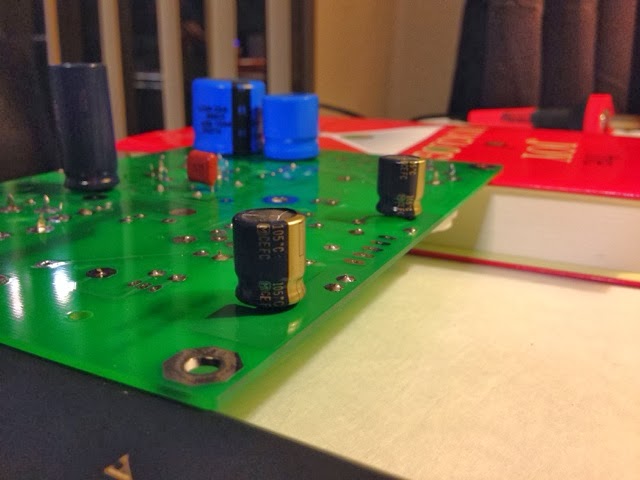
Added the tube sockets and capacitors tonight, most of them. I'm using the inverted assembly method in order to mount the board to a chassis and have only the tubes show through. Resistors don't matter because they are so small, but this impacted a few things in my component attachment today.

For the sockets, there are three octal and one noval socket. The instructions on the Tubelab website show how you can elevate the mini noval socket so it might be flush with the others when the board is mounted to the underside of the chassis cover. So I did this, using a small stack of Pokemon cards to get the right height to allow the connectors to just barely show through the surface of the board when I soldered it on. Even so, my noval socket is so much smaller than the octals though that I question if it will still be high enough. We'll see.

For the capacitors, I mounted them to the bottom of the board, and needed to ensure the correct polarity for the electrolytic ones. These have a stripe or other indicator to show which is positive and negative. Seems to have been pretty easy. The one mistake I made was that I ordered two of the capacitors rated at 85 degrees celcius, and the instructions recommend 105 to better handle heat of operation. I might replace these later, but thought it would be ok to proceed and hopefully this is just a matter of reduced capacitor life, not risk of explosion or other such deadly matters.

I do not yet have the coupling capacitors. I was going to order some nice Auricaps, but these were about $12 each, and I'm thinking I just want to get some sound out of this thing without spending a fortune, so I bought some cheaper ones and waiting for delivery. I also ordered my transformers today and that set me back around $140 including shipping for all three. I can replace the coupling caps later if desired to improve the sound.